
UG103.11: Thread Fundamentals
This document includes a brief background on the emergence of
Thread, provides a technology overview, and describes some
key features of Thread to consider when implementing a Thread
solution.
Silicon Labs’ Fundamentals series covers topics that project managers, application de-
signers, and developers should understand before beginning to work on an embedded
networking solution using Silicon Labs chips, networking stacks such as EmberZNet
PRO or Silicon Labs Bluetooth
®
, and associated development tools. The documents
can be used as a starting place for anyone needing an introduction to developing wire-
less networking applications, or who is new to the Silicon Labs development environ-
ment.
KEY POINTS
• Introduces Thread and provides a
technology overview.
• Describes some of the key elements of
Thread, including its IP stack, network
topology, routing and network connectivity,
joining a network, management, persistent
data, security, border router, device
commissioning, and application layer.
• Contains updates for Thread Specification
1.3.0.
• Includes next steps for working with the
Silicon Labs OpenThread offering.
silabs.com | Building a more connected world. Copyright © 2024 by Silicon Laboratories Rev. 1.6

1. Introduction
1.1 Silicon Labs and the Internet of Things
Internet Protocol version 4 (IPv4) was defined in 1981 in RFC 791, DARPA Internet Program Protocol Specification. ("RFC" stands for
"Request for Comments.") Using 32-bit (4-byte) addressing, IPv4 provided 232 unique addresses for devices on the internet, a total of
approximately 4.3 billion addresses. However, as the number of users and devices grew exponentially, it was clear that the number of
IPv4 addresses would be exhausted and there was a need for a new version of the IP. Hence the development of IPv6 in the 1990s
and its intention to replace IPv4. With 128-bit (16-byte) addressing, IPv6 allows for 2128 addresses, more than 7.9x1028 addresses
than IPv4 (http://en.wikipedia.org/wiki/IPv6).
The challenge for companies in the embedded industry like Silicon Labs is to address this technology migration and more importantly
the demands of customers as we move to an ever-connected world of devices in the home and commercial space, what is often refer-
red to as the Internet of Things (IoT). At a high level the goals of IoT for Silicon Labs are to:
• Connect all the devices in the home and commercial space with best-in-class networking, whether with Zigbee PRO, Thread, Blue-
tooth, or other emerging standards.
• Leverage the company's expertise in energy-friendly microcontrollers.
• Enhance established low-power, mixed-signal chips.
• Provide low-cost bridging to existing Ethernet and Wi-Fi devices.
• Enable cloud services and connectivity to smartphones and tablets that will promote ease of use and a common user experience for
customers.
Achieving all of these goals will increase adoption rates and user acceptance for IoT devices.
1.2 Thread Group
Thread Group (https://www.threadgroup.org/) was launched on July 15, 2014. Silicon Labs was a founding company along with six oth-
er companies. Thread Group is a market education group that offers product certification and promotes the use of Thread-enabled de-
vice-to-device (D2D) and machine-to-machine (M2M) products. Membership in Thread Group is open.
Thread Specification 1.1 may be downloaded after submitting a request here: https://www.threadgroup.org/ThreadSpec. Successor ver-
sions of the Thread Specification, 1.2 and 1.3.0, have also been announced with certification programs in 2022. The latest 1.4-draft
Thread specification is only available to Thread members.
UG103.11: Thread Fundamentals
Introduction
silabs.com | Building a more connected world. Rev. 1.6 | 2
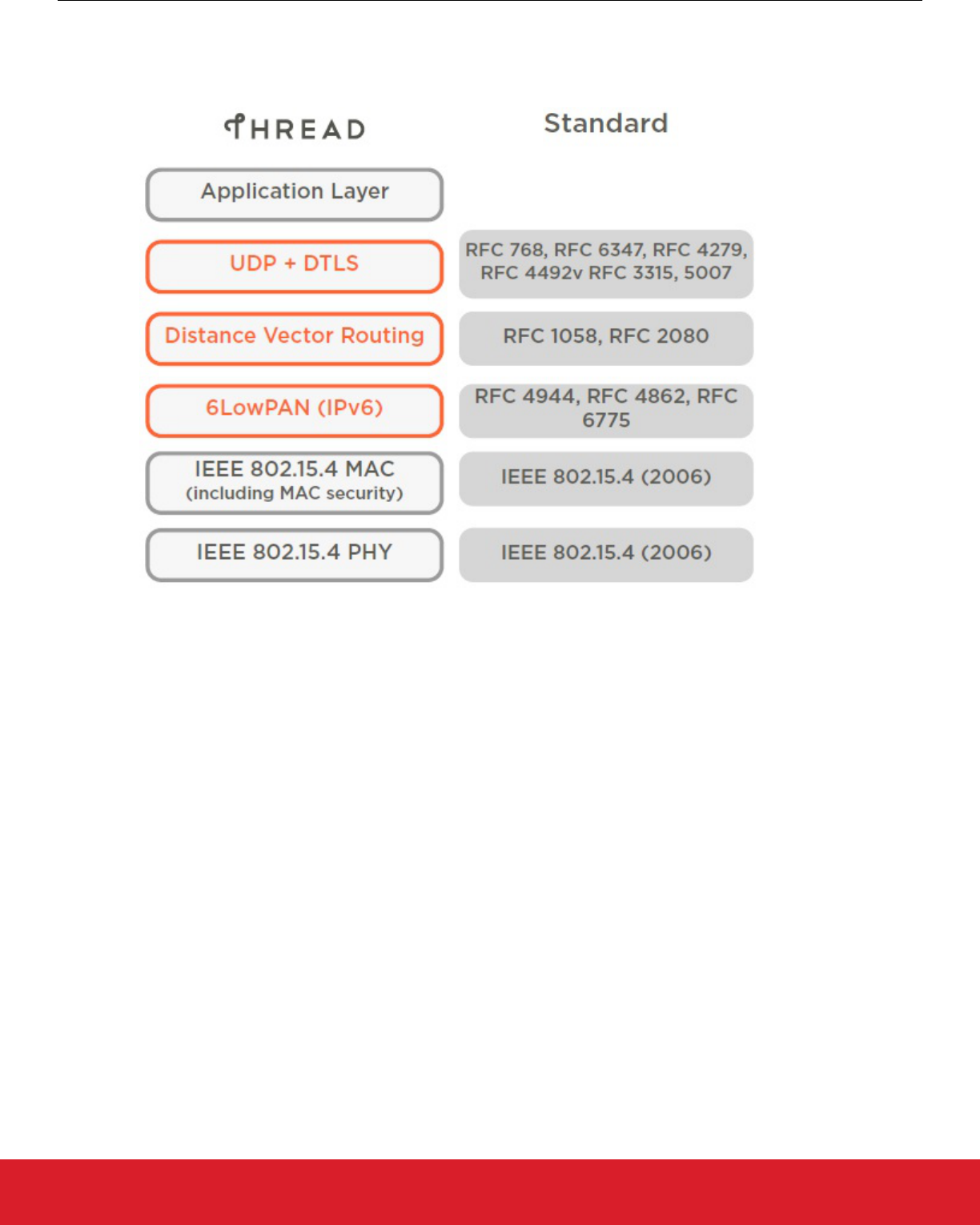
1.3 What is Thread?
Thread is a secure, wireless mesh networking protocol. The Thread stack is an open standard that is built upon a collection of existing
Institute for Electrical and Electronics Engineers (IEEE) and Internet Engineering Task Force (IETF) standards, rather than a whole new
standard (see the following figure).
Figure 1.1. Thread Stack Overview
UG103.11: Thread Fundamentals
Introduction
silabs.com | Building a more connected world. Rev. 1.6 | 3

1.4 Thread General Characteristics
The Thread stack supports IPv6 addresses and provides low-cost bridging to other IP networks and is optimized for low-power / bat-
tery-backed operation, and wireless device-to-device communication. The Thread stack is designed specifically for Connected Home
and commercial applications where IP-based networking is desired and a variety of application layers can be used on the stack.
These are the general characteristics of the Thread stack:
• Simple network installation, start-up, and operation: The Thread stack supports several network topologies. Installation is simple
using a smartphone, tablet, or computer. Product installation codes are used to ensure only authorized devices can join the network.
The simple protocols for forming and joining networks allow systems to self-configure and fix routing problems as they occur.
• Secure: Devices do not join the network unless authorized and all communications are encrypted and secure. Security is provided
at the network layer and can be at the application layer. All Thread networks are encrypted using a smartphone-era authentication
scheme and Advanced Encryption Standard (AES) encryption. The security used in Thread networks is stronger than other wireless
standards the Thread Group has evaluated.
• Small and large home networks: Home networks vary from several to hundreds of devices. The networking layer is designed to
optimize the network operation based on the expected use.
• Large commercial networks: For larger commercial installations, a single Thread network is not sufficient to cover all the applica-
tion, system and network requirements. The Thread Domain model allows scalability for up to 10,000s of Thread devices in a single
deployment, using a combination of different connectivity technologies (Thread, Ethernet, Wi-fi, and so on).
• Bi-directional service discovery and connectivity: Multicast and broadcast are inefficient on wireless mesh networks. For off-
mesh communication, Thread provides a service registry where devices can register their presence and services, and clients can
use unicast queries to discover the registered services.
• Range: Typical devices provide sufficient range to cover a normal home. Readily available designs with power amplifiers extend the
range substantially. A distributed spread spectrum is used at the Physical Layer (PHY) to be more immune to interference. For com-
mercial installations, the Thread Domain model allows multiple Thread networks to communicate with each other over a backbone,
thus extending the range to cover many mesh subnets.
• No single point of failure: The Thread stack is designed to provide secure and reliable operations even with the failure or loss of
individual devices. Thread devices can also incorporate IPv6-based links such as Wi-Fi and Ethernet into the topology to reduce the
probability of multiple Thread partitions. This way, they can utilize the higher throughput, channel capacity, and coverage of those
infrastructure links, while still supporting low-power devices.
• Low power: Devices efficiently communicate to deliver an enhanced user experience with years of expected life under normal bat-
tery conditions. Devices can typically operate for several years on AA type batteries using suitable duty cycles.
• Cost-effective: Compatible chipsets and software stacks from multiple vendors are priced for mass deployment and designed from
the ground up to have extremely low-power consumption.
1.5 OpenThread
OpenThread released by Google is an open-source implementation of Thread®. Google has released OpenThread to make the net-
working technology used in Google Nest products more broadly available to developers, in order to accelerate the development of prod-
ucts for the connected home and commercial buildings.
With a narrow platform abstraction layer and a small memory footprint, OpenThread is highly portable. It supports both system-on-chip
(SoC) and radio co-processor (RCP) designs.
OpenThread defines an IPv6-based reliable, secure, and low-power wireless device-to-device communication protocol for home and
commercial building applications. It implements all features defined in Thread Specification 1.1.1, Thread Specification 1.2, Thread
Specification 1.3.0, and draft Thread Specification 1.4 (as of the release of this document).
Silicon Labs has implemented an OpenThread-based protocol tailored to work with Silicon Labs hardware. This protocol is available on
GitHub and also as a software development kit (SDK) installed with Simplicity Studio 5. The SDK is a fully tested snapshot of the Gi-
tHub source. It supports a broader range of hardware than does the GitHub version, and includes documentation and example applica-
tions not available on GitHub.
UG103.11: Thread Fundamentals
Introduction
silabs.com | Building a more connected world. Rev. 1.6 | 4

2. Thread Technology Overview
2.1 IEEE 802.15.4
The IEEE 802.15.4-2006 specification is a standard for wireless communication that defines the wireless Medium Access Control
(MAC) and Physical (PHY) layers operating at 250 kbps in the 2.4 GHz band, with a roadmap to subGHz bands (IEEE 802.15.4-2006
Specification). Designed with low power in mind, 802.15.4 is suitable for applications usually involving a large number of nodes.
The 802.15.4 MAC layer is used for basic message handling and congestion control. This MAC layer includes a Carrier Sense Multiple
Access (CSMA) mechanism for devices to listen for a clear channel, as well as a link layer to handle retries and acknowledgement of
messages for reliable communications between adjacent devices. MAC layer encryption is used on messages based on keys establish-
ed and configured by the higher layers of the software stack. The network layer builds on these underlying mechanisms to provide relia-
ble end-to-end communications in the network.
Starting with Thread Specification 1.2, several optimizations from the IEEE 802.15.4-2015 specification have been implemented to
make Thread networks more robust, responsive and scalable:
• Enhanced Frame Pending: Improves the battery life and responsiveness of a sleepy end device (SED), by reducing the number of
messages a SED can send over the air. Any data packet that arrives from an SED (not just data requests) can be acknowledged
with the presence of upcoming pending data.
• Enhanced Keepalive: Reduces the amount of traffic required to maintain a link between a SED and a parent by treating any data
message as a keepalive network transmission.
• Coordinated Sampled Listening (CSL): This IEEE 802.15.4-2015 Specification feature allows for better synchronization between a
SED and a parent by scheduling synchronized transmit/receive periods without periodic data requests. This enables low-power devi-
ces that have low link latency and a network with a lower chance of message collisions.
• Enhanced ACK Probing: This IEEE 802.15.4-2015 Specification feature allows an initiator granular control over link metric queries
while saving energy by reusing regular data traffic patterns rather than separate probe messages.
UG103.11: Thread Fundamentals
Thread Technology Overview
silabs.com | Building a more connected world. Rev. 1.6 | 5
2.2 Thread Network Architecture
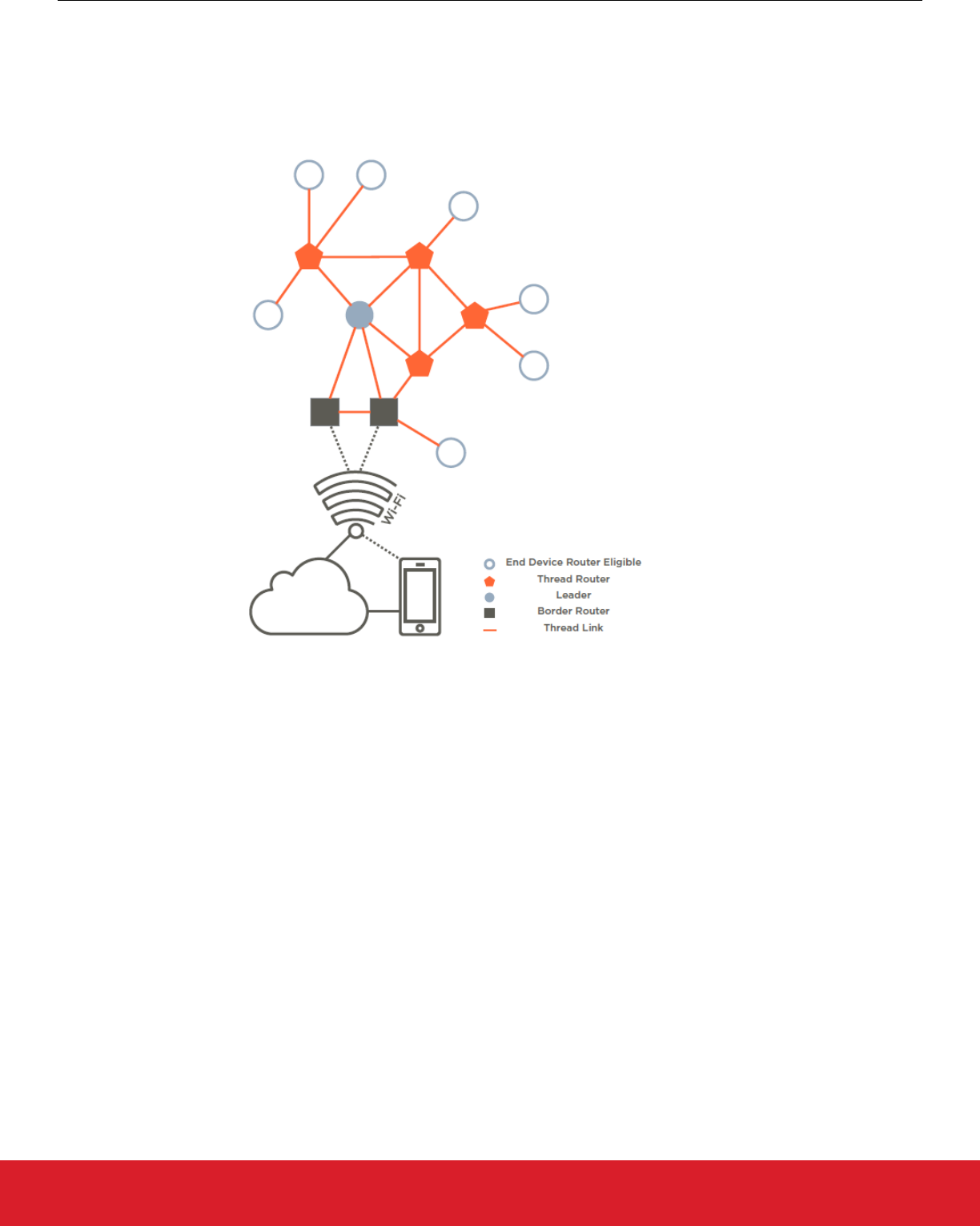
2.2.1 Residential Architecture
Users communicate with a residential Thread network from their own device (smartphone, tablet, or computer) via Wi-Fi on their Home
Area Network (HAN) or using a cloud-based application. The following figure illustrates the key device types in the Thread network ar-
chitecture.
Figure 2.1. Thread Network Architecture
The following device types are included in a Thread network, starting from the Wi-Fi network:
• Border Routers provide connectivity from the 802.15.4 network to adjacent networks on other physical layers (Wi-Fi, Ethernet, etc.).
Border Routers provide services for devices within the 802.15.4 network, including routing services and service discovery for off net-
work operations. There may be one or more Border Routers in a Thread network.
• A Leader, in a Thread network partition, manages a registry of assigned router IDs and accepts requests from router-eligible end
devices (REEDs) to become routers. The Leader decides which should be routers, and the Leader, like all routers in a Thread net-
work, can also have device-end children. The Leader also assigns and manages router addresses using CoAP (Constrained Appli-
cation Protocol). However, all information contained in the Leader is present in the other Thread Routers. So, if the Leader fails or
loses connectivity with the Thread network, another Thread Router is elected, and takes over as Leader without user intervention.
• Thread Routers provide routing services to network devices. Thread Routers also provide joining and security services for devices
trying to join the network. Thread Routers are not designed to sleep and can downgrade their functionality and become REEDs.
• REEDs can become a Thread Router or a Leader, but not necessarily a Border Router that has special properties, such as multiple
interfaces. Because of the network topology or other conditions, REEDs do not act as routers. REEDs do not relay messages or
provide joining or security services for other devices in the network. The network manages and promotes router-eligible devices to
routers if necessary, without user interaction.
• End devices that are not router-eligible can be either FEDs (full end devices) or MEDs (minimal end devices). MEDs do not need to
explicitly synchronize with their parent to communicate.
• Sleepy end devices (SEDs) communicate only through their Thread Router parent and cannot relay messages for other devices.
• Synchronized Sleepy End Devices (SSEDs) are a class of Sleepy End Devices that use CSL from IEEE 802.15.4-2015 to main-
tain a synchronized schedule with a parent, avoiding the use of regular data requests.
UG103.11: Thread Fundamentals
Thread Technology Overview
silabs.com | Building a more connected world. Rev. 1.6 | 6
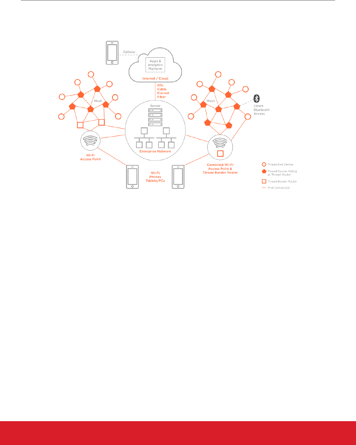
2.2.2 Commercial Architecture
The Thread Commercial model takes the key device types for a residential network and adds new concepts. Users communicate with a
commercial network through devices (smartphone, tablet, or computer) via Wi-Fi or through their enterprise network. The following fig-
ure illustrates a commercial network topology.
Figure 2.2. Commercial Network Topology
The concepts are:
• The Thread Domain model supports seamless integration of multiple Thread Networks as well as seamless interface to non-Thread
IPv6 networks. The main benefit of the Thread Domain is that devices are to some extent flexible to join any available Thread Net-
work configured with a common Thread Domain, which reduces the need for manual network planning or costly manual reconfigura-
tions when network size or data volume are scaled up.
• Backbone Border Routers (BBRs) are a class of Border Router in the commercial space which facilitate Thread Domain synchroni-
zation of multiple network segments and allow large scope multicast propagation into and out of each single mesh in a Thread Do-
main. A Thread network that is part of a larger domain must have at least one “Primary” BBR and can have multiple “Secondary”
BBRs for fail-safe redundancy. The BBRs communicate with each other over a backbone which connects all the Thread networks.
• A Backbone Link is a non-Thread IPv6 link to which a BBR connects using an external interface used to implement the Thread
Backbone Link Protocol (TBLP) to synchronize with other BBRs.
• Thread Devices in a commercial implementation are configured using Thread Domains and Domain Unique Addresses (DUAs). A
device’s DUA never changes over its lifetime of being part of a Thread domain. This facilitates migration across different Thread
networks in a single domain and makes sure that the respective BBRs facilitate routing across multiple Thread networks.
These concepts are illustrated in the following figure:
UG103.11: Thread Fundamentals
Thread Technology Overview
silabs.com | Building a more connected world. Rev. 1.6 | 7
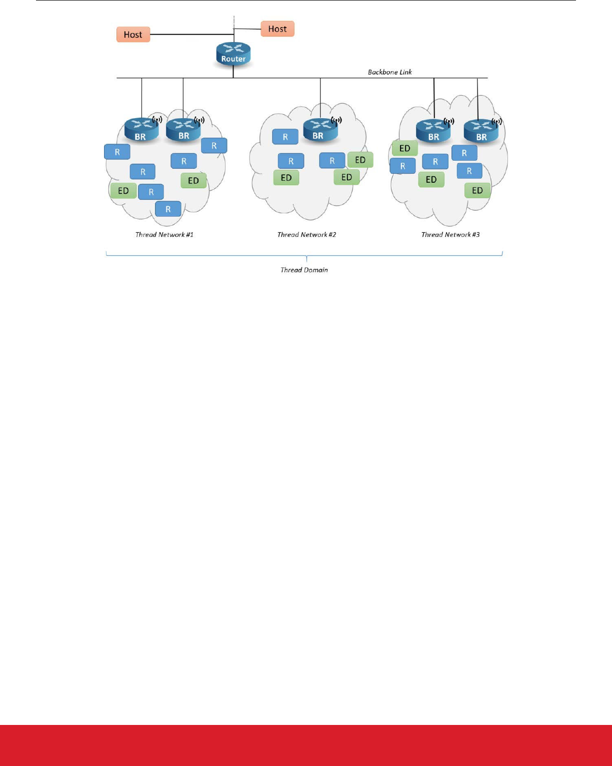
Figure 2.3. Thread Domain Model
2.3 No Single Point of Failure
The Thread stack is designed to not have a single point of failure. While there are a number of devices in the system that perform
special functions, Thread is designed so they can be replaced without impacting the ongoing operation of the network or devices. For
example, a sleepy end device requires a parent for communications, so this parent represents a single point of failure for its communi-
cations. However, the sleepy end device can and will select another parent if its parent is unavailable. This transition should not be
visible to the user.
While the system is designed for no single point of failure, under certain topologies there will be individual devices that do not have
backup capabilities. For example, in a system with a single Border Router, if the Border Router loses power, there is no means to
switch to an alternative Border Router. In this scenario, a reconfiguration of the Border Router must take place.
Starting with Thread Specification 1.3.0, Border Routers sharing an infrastructure link can facilitate no-single point of failure across a
different medium (such as Wi-Fi or Ethernet) by utilizing a Thread Radio Encapsulation Link (TREL). With this feature, the probability of
Thread partitions forming across links is reduced.
UG103.11: Thread Fundamentals
Thread Technology Overview
silabs.com | Building a more connected world. Rev. 1.6 | 8
3. IP Stack Fundamentals
3.1 Addressing
Devices in the Thread stack support IPv6 addressing architecture as defined in RFC 4291 (https://tools.ietf.org/html/rfc4291: IP Version
6 Addressing Architecture). Devices support a Unique Local Address (ULA), a Domain Unique Address (DUA) in a Thread domain
model, and one or more Global Unicast Address (GUA) addresses based on their available resources.
The high-order bits of an IPv6 address specify the network and the rest specify particular addresses in that network. Thus, all the ad-
dresses in one network have the same first N bits. Those first N bits are called the "prefix". The "/64" indicates that this is an address
with a 64-bit prefix. The device starting the network picks a /64 prefix that is then used throughout the network. The prefix is a ULA
(https://tools.ietf.org/html/rfc4193: Unique Local IPv6 Unicast Addresses). The network may also have one or more Border Router(s)
that each may or may not have a /64 that can then be used to generate a ULA or GUA. The device in the network uses its EUI-64 (64-
bit Extended Unique Identifier) address to derive its interface identifier as defined in Section 6 of RFC 4944 (https://tools.ietf.org/html/
rfc4944: Transmission of IPv6 Packets over IEEE 802.15.4 Networks ). The device will support a link local IPv6 address configured
from the EUI-64 of the node as an interface identifier with the well-known link local prefix FE80::0/64 as defined in RFC 4862 (https://
tools.ietf.org/html/rfc4862: IPv6 Stateless Address Autoconfiguration) and RFC 4944.
The devices also support appropriate multicast addresses. This includes link-local all node multicast, link local all router multicast, soli-
cited node multicast, and a mesh local multicast. With the presence of a backbone border router in a domain model, devices can also
support higher scope multicast addresses if they register for them.
Each device joining the network is assigned a 2-byte short address as per the IEEE 802.15.4-2006 specification. For routers, this ad-
dress is assigned using the high bits in the address field. Children are then assigned a short address using their parent’s high bits and
the appropriate lower bits for their address. This allows any other device in the network to understand the child’s routing location by
using the high bits of its address field.
3.2 6LoWPAN
6LoWPAN stands for “IPv6 Over Low Power Wireless Personal Networks.” The main goal of 6LoWPAN is to transmit and receive IPv6
packets over 802.15.4 links. In doing so it has to accommodate for the 802.15.4 maximum frame size sent over the air. In Ethernet
links, a packet with the size of the IPv6 Maximum Transmission Unit (MTU) (1280 bytes) can be easily sent as one frame over the link.
In the case of 802.15.4, 6LoWPAN acts as an adaptation layer between the IPv6 networking layer and the 802.15.4 link layer. It solves
the issue of transmitting an IPv6 MTU by fragmenting the IPv6 packet at the sender and reassembling it at the receiver.
6LoWPAN also provides a compression mechanism that reduces the IPv6 header sizes sent over the air and thus reduces transmission
overhead. The fewer bits that are sent over the air, the less energy is consumed by the device. Thread makes full use of these mecha-
nisms to efficiently transmit packets over the 802.15.4 network. RFC 4944 (https://tools.ietf.org/html/rfc4944) and RFC 6282 (https://
tools.ietf.org/html/rfc6282) describe in detail the methods by which fragmentation and header compression are accomplished.
3.3 Link Layer Forwarding
Another important feature of the 6LoWPAN layer is link layer packet forwarding. This provides a very efficient and low overhead mecha-
nism for forwarding multi hop packets in a mesh network. Thread uses IP layer routing with link layer packet forwarding.
Thread uses the link layer forwarding to forward packets based on the IP routing table. In order to accomplish this, the 6LoWPAN mesh
header is used in each multi-hop packet (see the following figure).
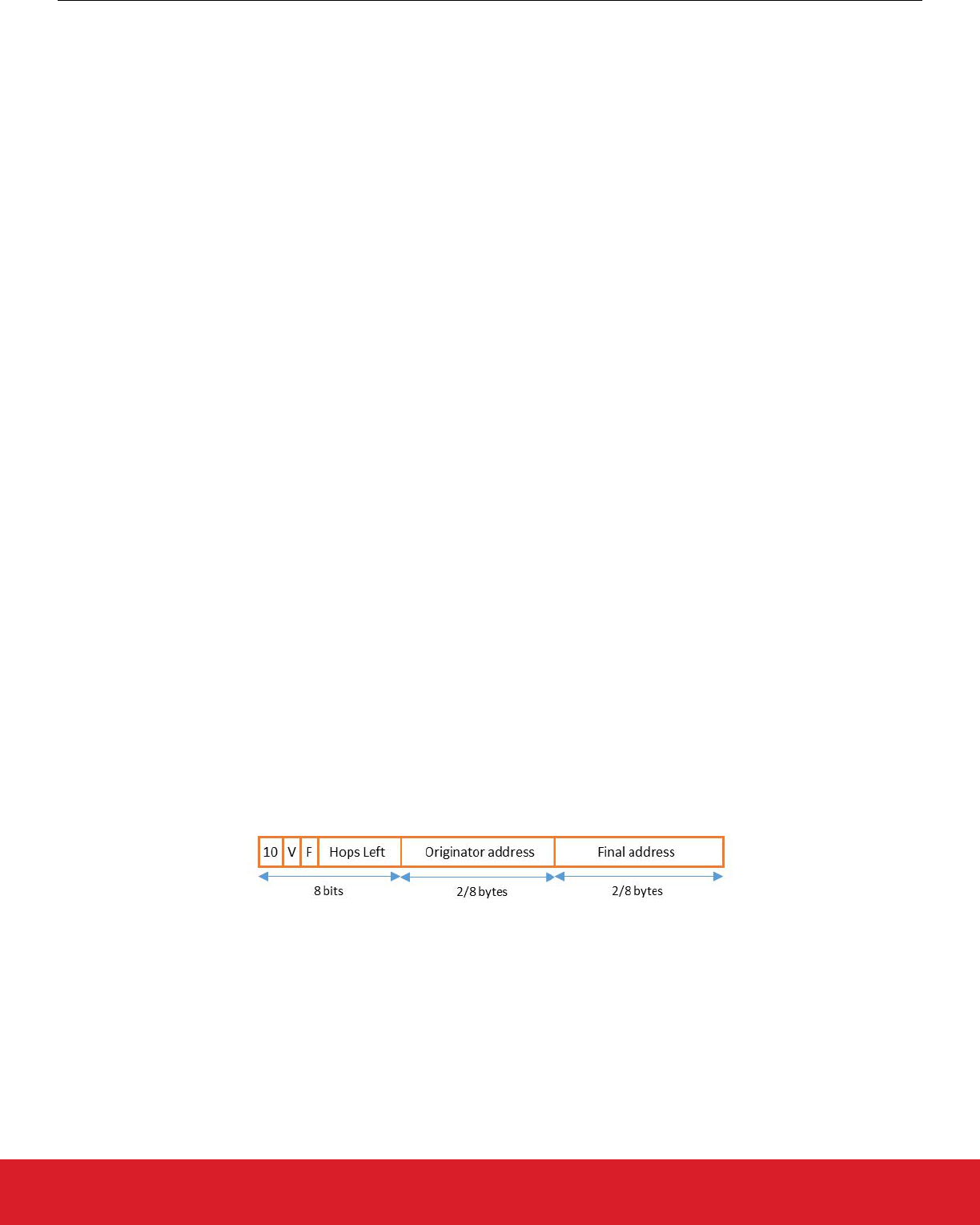
Figure 3.1. Mesh Header Format
In Thread, the 6LoWPAN layer fills the Mesh Header information with the originator 16-bit short address and final destination 16-bit
source address. The transmitter looks up the next hop 16-bit short address in the Routing Table, and then sends the 6LoWPAN frame
to the next hop 16-bit short address as destination. The next hop device receives the packet, looks up the next hop in the Routing
Table / Neighbor Table, decrements the hop count in the 6LoWPAN Mesh Header, and then sends the packet to the next hop or final
destination 16-bit short address as destination.
UG103.11: Thread Fundamentals
IP Stack Fundamentals
silabs.com | Building a more connected world. Rev. 1.6 | 9
3.4 6LoWPAN Encapsulation
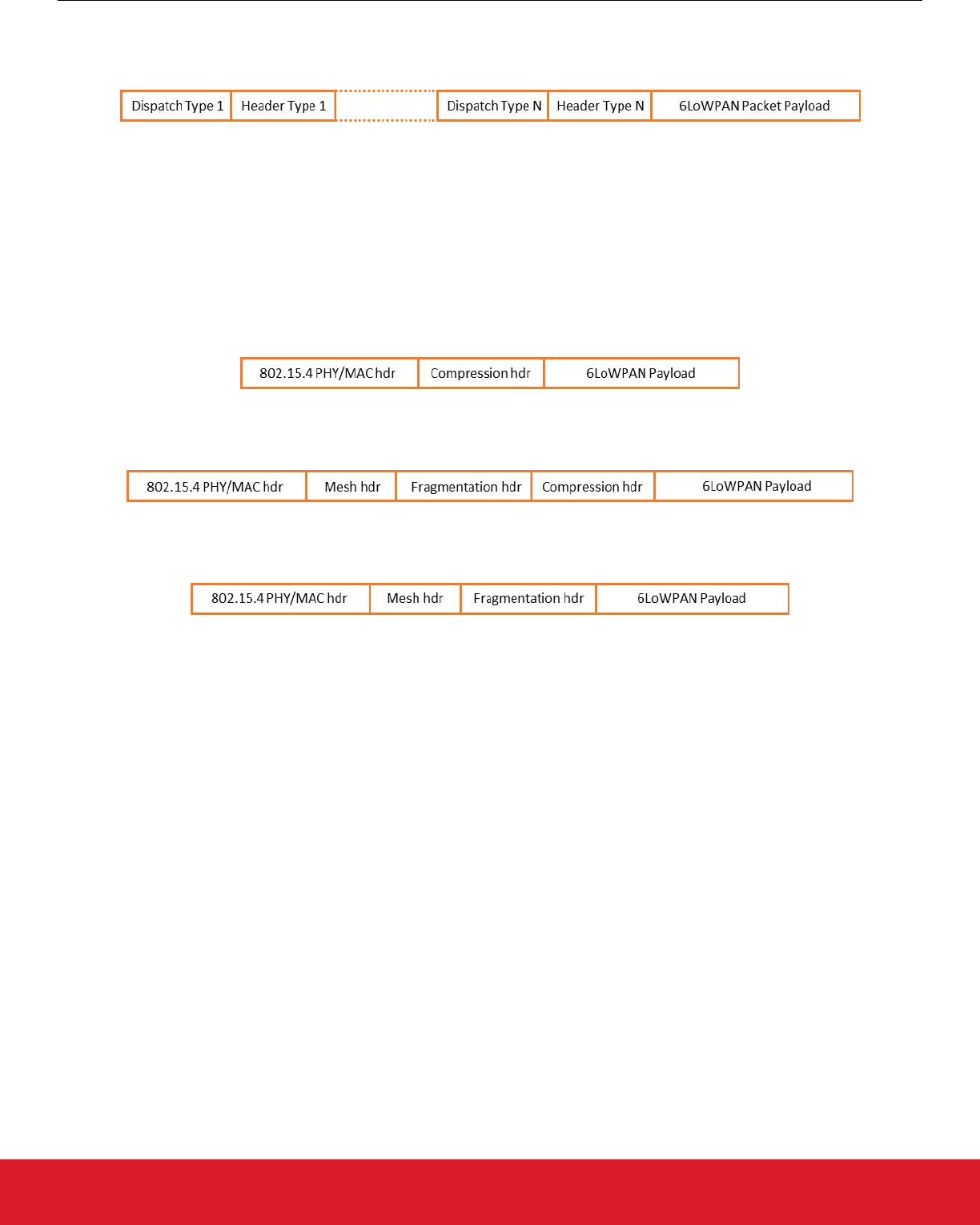
6LoWPAN packets are constructed on the same principle as IPv6 packets and contain stacked headers for each added functionality.
Each 6LoWPAN header is preceded by a dispatch value that identifies the type of header (see the following figure).
Figure 3.2. General Format of a 6LoWPAN Packet
Thread uses the following types of 6LoWPAN headers:
• Mesh Header (used for link layer forwarding)
• Fragmentation Header (used for fragmenting the IPv6 packet into several 6LoWPAN packets)
• Header Compression Header (used for IPv6 headers compression)
The 6LoWPAN specification mandates that if more than one header is present, they must appear in the order mentioned above.
The following are examples of 6LoWPAN packets sent over the air.
In the following figure, the 6LoWPAN payload is composed of the compressed IPv6 header and the rest of the IPv6 payload.
Figure 3.3. 6LoWPAN Packet Containing IPv6 Payload with Compressed IPv6 Header
In the following figure, the 6LoWPAN payload contains the IPv6 header and part of the IPv6 payload.
Figure 3.4. 6LoWPAN Packet Containing Mesh Header, a Fragmentation Header, and a Compression Header
The rest of the payload will be transmitted in subsequent packets per the format in the following figure.
Figure 3.5. 6LoWPAN Subsequent Fragment
3.5 ICMP
Thread devices support the Internet Control Message Protocol version 6 (ICMPv6) protocol as defined in RFC 4443, Internet Control
Message Protocol (ICMPv6) for the Internet Protocol Version 6 (IPv6) Specification. They also support the echo request and echo reply
messages.
3.6 UDP
The Thread stack supports User Datagram Protocol (UDP) as defined in RFC 768, User Datagram Protocol.
3.7 TCP
The Thread stack supports a Transport Control Protocol (TCP) variant called “TCPlp" (TCP Low Power) (See usenix-NSDI20). A
Thread-compliant device implements the TCP initiator and listener roles as described in:
• RFC 793, Transmission Control Protocol
• RFC 1122, Requirements for Internet Hosts
• Thread Specification 1.3.0 and higher: Existing TCP implementations are typically not tuned to work optimally over wireless mesh
networks and with the limited 802.15.4 frame sizes. Therefore, the specification defines those elements and parameter values re-
quired for an efficient TCP implementation over Thread Networks (see Thread Specification 1.3.0, section 6.2 TCP).
UG103.11: Thread Fundamentals
IP Stack Fundamentals
silabs.com | Building a more connected world. Rev. 1.6 | 10

3.8 SRP
Service Registration Protocol (SRP) as defined in Service Registration Protocol for DNS-Based Service Discovery is utilized on Thread
devices starting with Thread Specification 1.3.0. There must exist a Service Registry, maintained by a border router. SRP clients on the
mesh network can register to offer various services. An SRP server accepts DNS-based discovery queries and additionally offers public
key cryptography for security, along with other minor enhancements to better support constrained clients.
UG103.11: Thread Fundamentals
IP Stack Fundamentals
silabs.com | Building a more connected world. Rev. 1.6 | 11

4. Network Topology
4.1 Network Address and Devices
The Thread stack supports full mesh connectivity between all routers in the network. The actual topology is based on the number of
routers in the network. If there is only one router, then the network forms a star. If there is more than one router then a mesh is auto-
matically formed (see 2.2 Thread Network Architecture).
4.2 Mesh Networks
Embedded mesh networks make radio systems more reliable by allowing radios to relay messages for other radios. For example, if a
node cannot send a message directly to another node, the embedded mesh network relays the message through one or more interme-
diary nodes. As discussed in section 5.3 Routing, all router nodes in the Thread stack maintain routes and connectivity with each other
so the mesh is constantly maintained and connected. There is a limit of 64 router addresses in the Thread network, but they cannot all
be used at once. This allows time for the addresses of deleted devices to be reused.
In a mesh network, the sleepy end devices or router-eligible devices do not route for other devices. These devices send messages to a
parent that is a router. This parent router handles the routing operations for its child devices.
UG103.11: Thread Fundamentals
Network Topology
silabs.com | Building a more connected world. Rev. 1.6 | 12

5. Routing and Network Connectivity
The Thread network has up to 32 active routers that use next-hop routing for messages based on the routing table. The routing table is
maintained by the Thread stack to ensure all routers have connectivity and up-to-date paths for any other router in the network. All
routers exchange with other routers their cost of routing to other routers in the network in a compressed format using Mesh Link Estab-
lishment (MLE).
5.1 MLE Messages
Mesh Link Establishment (MLE) messages are used to establish and configure secure radio links, detect neighboring devices, and
maintain routing costs between devices in the network. MLE operates below the routing layer and uses one hop link local unicasts and
multicasts between routers.
MLE messages are used to identify, configure, and secure links to neighboring devices as the topology and physical environment
change. MLE is also used to distribute configuration values that are shared across the network such as the channel and Personal Area
Network (PAN) ID. These messages can be forwarded with simple flooding as specified by MPL (https://tools.ietf.org/html/draft-ietf-roll-
trickle-mcast-11: Multicast Protocol for Low power and Lossy Networks (MPL)).
MLE messages also ensure asymmetric link costs are considered when establishing routing costs between two devices. Asymmetric
link costs are common in 802.15.4 networks. To ensure two-way messaging is reliable, it is important to consider bidirectional link
costs.
5.2 Route Discovery and Repair
On-demand route discovery is commonly used in low-power 802.15.4 networks. However, on-demand route discovery is costly in terms
of network overhead and bandwidth because devices broadcast route discovery requests through the network. In the Thread stack, all
routers exchange one-hop MLE packets containing cost information to all other routers in the network. All routers have up-to-date path
cost information to any other router in the network so on-demand route discovery is not required. If a route is no longer usable, the
routers can select the next most suitable route to the destination.
Routing to child devices is done by looking at the high bits of the child’s address to determine the parent router address. Once the
device knows the parent router, it knows the path cost information and next hop routing information for that device.
As route cost or the network topology change, the changes propagate through the network using the MLE single-hop messages. Rout-
ing cost is based on bidirectional link quality between two devices. The link quality in each direction is based on the link margin on
incoming messages from that neighboring device. This incoming Received Signal Strength Indicator (RSSI) is mapped to a link quality
from 0 to 3. A value of 0 means unknown cost.
When a router receives a new MLE message from a neighbor, either it already has a neighbor table entry for the device or one is add-
ed. The MLE message contains the incoming cost from the neighbor, so this is updated in the router’s neighbor table. The MLE mes-
sage also contains updated routing information for other routers which is updated in the routing table.
The number of active routers is limited to the amount of routing and cost information that can be contained in a single 802.15.4 packet.
This limit is currently 32 routers.
UG103.11: Thread Fundamentals
Routing and Network Connectivity
silabs.com | Building a more connected world. Rev. 1.6 | 13

5.3 Routing
Devices use normal IP routing to forward packets. A routing table is populated with network addresses and the appropriate next hop.
Distance vector routing is used to get routes to addresses that are on the local network. When routing on the local network, the upper
six bits of this 16-bit address define the router destination. This routing parent is then responsible for forwarding to the final destination
based on the remainder of the 16-bit address.
For off network routing, a Border Router notifies the Router Leader of the particular prefixes it serves and distributes this information as
network data within the MLE packets. The network data includes prefix data, which is the prefix itself, the 6LoWPAN context, the Border
Routers, and the Stateless Address Autoconfiguration (SLAAC) or DHCPv6 server for that prefix. If a device is to configure an address
using that prefix, it contacts the appropriate SLAAC or DHCP server for this address. The network data also includes a list of routing
servers that are the 16-bit addresses of the default Border Routers.
Additionally, in a commercial space with a Thread Domain model, a Backbone Border Router notifies the router leader of the Domain
Unique Prefix it serves, to indicate that this mesh is part of the larger Thread domain. The network data for this includes prefix data,
6LoWPAN context, and the border router ALOC. There are no SLAAC or DHCPv6 flags set for this prefix set, however the address
assignment follows the stateless model. Additionally, there are also service and server TLVs indicating the “backbone” service capabili-
ty of this border router. Duplicate address detection capability over the backbone exists for any device that registers its Domain Unique
Address (DUA) with the BBR. A device’s DUA never changes over its lifetime of being part of a Thread domain. This facilitates migra-
tion across different Thread networks in a single domain and makes sure that the respective BBRs facilitate routing across multiple
Thread networks. Over the backbone, standard IPv6 routing technologies such as IPv6 Neighbor Discovery (NS/NA as per RFC 4861)
and Multicast Listener Discovery (MLDv2 as per RFC 3810) are used.
A Leader is designated to keep track of router-eligible devices becoming routers or allowing routers to downgrade to router-eligible de-
vices. This Leader also assigns and manages the router addresses using CoAP. However, all information contained in this Leader is
also periodically advertised to the other routers. If the Leader goes off the network, another router is elected, and takes over as Leader
without user intervention.
Border Routers are responsible for handling 6LoWPAN compression or expansion and addressing to off network devices. Backbone
Border Routers are responsible for handling MPL with IP-in-IP encapsulation and decapsulation for larger scope multicasts going into
and out of the mesh.
For more information on Border Routers, see AN1256: Using the Silicon Labs RCP with the OpenThread Border Router.
5.4 Retries and Acknowledgements
While UDP messaging is used in the Thread stack, reliable message delivery is required and completed by these lightweight mecha-
nisms:
• MAC-level retries–each device uses MAC acknowledgements from the next hop and will retry a message at the MAC layer if the
MAC ACK message is not received.
• Application-layer retries– the application layer can determine if message reliability is a critical parameter. If so, an end-to-end ac-
knowledgement and retry protocol can be used, such as CoAP retries.
UG103.11: Thread Fundamentals
Routing and Network Connectivity
silabs.com | Building a more connected world. Rev. 1.6 | 14

6. Joining and Network Operation
Thread allows two joining methods:
• Share commissioning information directly to a device using an out-of-band method. This allows steering the device to the proper
network using this information.
• Establish a commissioning session between a joining device and a commissioning application on a smartphone, tablet, or the web.
• For a commercial network with a Thread domain model, an Autonomous Enrollment process without user intervention that provi-
sions operational certificates on joiners after authentication is specified by Thread Specification 1.2. The operational certificate enco-
des the domain information for the device and allows secure Network Master Key provision. This model requires a registrar or
Thread Registrar Interface (TRI) on a backbone border router and facilitates communication with an external authority (MASA) using
the ANIMA/BRSKI/EST protocols. A network that supports this commissioning model is called a CCM network.
For more information on commissioning Thread networks, see section 11. Device Commissioning.
The frequently used 802.15.4 method of joining with the permit joining flag in the beacon payload is not used in Thread networks. This
method is most commonly used for push button type joining where there is no user interface or out-of-band channel to devices. This
method has issues with device steering in situations where there are multiple networks available and it can also pose security risks.
In Thread networks, all joining is user-initiated. After joining, a security authentication is completed at the application level with a com-
missioning device. This security authentication is discussed in section 9. Security.
Devices join a network as either a sleepy end device, end device (MED or FED), or a REED. Only after a REED has joined and learned
the network configuration can it potentially request to become a Thread Router. Upon joining, a device is provided a 16-bit short ad-
dress based on its parent. If a router-eligible device becomes a Thread Router, it is assigned a router address by the Leader. Duplicate
address detection for Thread Routers is ensured by the centralized router address distribution mechanism which resides on the Leader.
The parent is responsible for avoiding duplicate addresses for host devices because it assigns addresses to them upon joining.
6.1 Network Discovery
Network discovery is used by a joining device to determine what 802.15.4 networks are within radio range. The device scans all chan-
nels, issues an MLE discovery request on each channel, and waits for MLE discovery responses. The 802.15.4 MLE discovery re-
sponse contains a payload with network parameters, including the network Service Set Identifier (SSID), extended PAN ID, and other
values that indicate if the network is accepting new members and whether it supports native commissioning.
Network discovery is not required if the device has been commissioned onto the network because it knows the channel and extended
PAN ID for the network. These devices then attach to the network using the commissioning material provided.
6.2 MLE Data
Once a device has attached to a network, there is a variety of information required for it to participate in the network. MLE provides
services for a device to send a unicast to a neighboring device to request network parameters and update link costs to neighbors.
When a new device joins, it also conducts a challenge response to set security frame counters as discussed in section 9. Security.
All devices support transmission and reception of MLE link configuration messages. This includes "link request", "link accept", and "link
accept and request" messages.
The MLE exchange is used to configure or exchange the following information:
• The 16-bit short and 64-bit EUI 64 long address of neighboring devices
• Device capabilities information, including if it is a sleepy end device and the sleep cycle of the device
• Neighbor link costs if a Thread Router
• Security material and frame counters between devices
• Routing costs to all other Thread Routers in the network
• Collecting and distributing Link Metrics about various link configuration values
Note: MLE messages are encrypted except during the initial node bootstrapping operations when the new device has not obtained
the security material.
UG103.11: Thread Fundamentals
Joining and Network Operation
silabs.com | Building a more connected world. Rev. 1.6 | 15

6.3 CoAP
Constrained Application Protocol (CoAP) as defined in RFC 7252 (https://tools.ietf.org/html/rfc7252: The Constrained Application Proto-
col (CoAP)) is a specialized transport protocol for use with constrained nodes and low-power networks. CoAP provides a request/
response interaction model between application endpoints, supports built-in discovery of services and resources, and includes key con-
cepts of the web such as URLs. CoAP is used in Thread to configure mesh-local addresses and multicast addresses required by
devices. Additionally, CoAP is also used for management messages such as to get and set diagnostic information and other network
data on active Thread routers.
6.4 DHCPv6
DHCPv6 as defined in RFC 3315 is used as a client-server protocol to manage configuration of devices within the network. DHCPv6
uses UDP to request data from a DHCP server (https://www.ietf.org/rfc/rfc3315.txt: Dynamic Host Configuration Protocol for IPv6
(DHCPv6)).
The DHCPv6 service is used for configuration of:
• Network addresses
• Multicast addresses required by devices
Because short addresses are assigned from the server using DHCPv6, duplicate address detection is not required. DHCPv6 is also
used by Border Routers that are assigning addresses based on the prefix they provide.
6.5 SLAAC
SLAAC (Stateless Address Autoconfiguration) as defined in RFC 4862 (https://tools.ietf.org/html/rfc4862: IPv6 Stateless Address Auto-
configuration) is a method in which a Border Router assigns a prefix, and then the last 64 bits of its address are derived by the router.
The IPv6 stateless autoconfiguration mechanism requires no manual configuration of hosts, minimal (if any) configuration of routers,
and no additional servers. The stateless mechanism allows a host to generate its own addresses using a combination of locally availa-
ble information and information advertised by routers.
6.6 SRP
Service Registration Protocol (SRP) as defined in Service Registration Protocol for DNS-Based Service Discovery is utilized on Thread
devices starting with Thread Specification 1.3.0. There must exist a Service Registry, maintained by a border router. SRP clients on the
mesh network can register to offer various services. An SRP server accepts DNS-based discovery queries and additionally offers public
key cryptography for security, along with other minor enhancements to better support constrained clients.
UG103.11: Thread Fundamentals
Joining and Network Operation
silabs.com | Building a more connected world. Rev. 1.6 | 16

7. Management
7.1 ICMP
All devices support Internet Control Message Protocol for IPv6 (ICMPv6) error messages, as well as the echo request and echo reply
messages.
7.2 Device Management
The application layer on a device has access to a set of device management and diagnostics information that can be used locally or
collected and sent to other management devices.
At the 802.15.4 PHY and MAC layers, the device provides the following information to the management layer:
• EUI 64 address
• 16-bit short address
• Capability information
• PAN ID
• Packets sent and received
• Octets sent and received
• Packets dropped on transmit or receive
• Security errors
• Number of MAC retries
7.3 Network Management
The network layer on the device also provides information on management and diagnostics that can be used locally or sent to other
management devices. The network layer provides the IPv6 address list, the neighbor and child table, and the routing table.
UG103.11: Thread Fundamentals
Management
silabs.com | Building a more connected world. Rev. 1.6 | 17

8. Persistent Data
Devices operating in the field may be reset accidentally or on purpose for a variety of reasons. Devices that have been reset need to
restart network operations without user intervention. For this to be done successfully, non-volatile storage must store the following infor-
mation:
• Network information (such as PAN ID)
• Security material
• Addressing information from the network to form the IPv6 addresses for the devices
UG103.11: Thread Fundamentals
Persistent Data
silabs.com | Building a more connected world. Rev. 1.6 | 18

9. Security
Thread networks are wireless networks that need to be secured against over-the-air (OTA) attacks. They are also connected to the
internet and therefore must be secured against internet attacks. Many of the applications being developed for Thread will serve a broad
range of uses that require long periods of unattended operation and low power consumption. As a result, the security of Thread net-
works is critical.
Thread utilizes a network-wide key that is used at the Media Access Layer (MAC) for encryption. This key is used for standard IEEE
802.15.4-2006 authentication and encryption. IEEE 802.15.4-2006 security protects the Thread network from over-the-air attacks origi-
nating from outside the network. Compromise of any individual node could potentially reveal the network-wide key. As a result, it is
usually not the only form of security used within the Thread network. Each node in the Thread network exchanges frame counters with
its neighbors via an MLE handshake. These frame counters help protect against replay attacks. (For more information on MLE, see the
Thread Specification.) Thread allows the application to use any internet security protocol for end-to-end communication.
Nodes obfuscate both their mesh-wide IP address interfaces and their MAC extended IDs by randomizing them. The stock EUI64 as-
signed to the node is used as a source address only during the initial join phase. Once a node is joined to a network, the node uses as
its source either an address based on its two-byte node ID, or one of its randomized addresses mentioned above. The EUI64 is not
used as a source address once the node is joined to a network.
Network management also needs to be secure. A Thread network management application can be run on any internet-connected de-
vice. If that device is not itself a member of a Thread network, it must first establish a secure Datagram Transport Layer Security
(DTLS) connection with a Thread Border Router. Every Thread network has a management passphrase that is used in establishing this
connection. Once a management application has been connected to the Thread network, new devices can be added to the network.
9.1 802.15.4 Security
The IEEE 802.15.4-2006 specification describes wireless and media access protocols for PANs and HANs. These protocols are intend-
ed for implementation on dedicated radio devices such as those available from Silicon Labs. IEEE 802.15.4-2006 supports a variety of
applications, many of which are security-sensitive. For example, consider the case of an alarm system application that monitors building
occupancy. If the network is not secure and an intruder gains access to the network, messages could be broadcast to create a false
alarm, modify an existing alarm, or silence a legitimate alarm. Each of these situations poses significant risks to the building occupants.
Many applications require confidentiality and most also need integrity protection. 802-15.4-2006 addresses these requirements by using
a link layer security protocol with four basic security services:
• Access control
• Message integrity
• Message confidentiality
• Replay protection
The replay protection provided by IEEE 802.15.4-2006 is only partial. Thread delivers additional security using MLE handshakes be-
tween nodes discussed above to complete the replay protection.
9.2 Secure Network Management
Network management also needs to be secure. A Thread network management application can be run on any internet-connected de-
vice. There are two parts to the security:
• Over-the-air security which 802.15.4 takes care of. Thread implements 802.15.4-2006 level 5 security.
• CCM networks: If a device is not itself a member of a CCM network, it must establish a connection with a backbone border router in
order to obtain its operational certificate to establish itself as part of the Thread domain.
• Non-CCM networks: Internet security: If a device is not itself a member of a Thread network, it must first establish a secure Data-
gram Transit Layer Security (DTLS) connection with a Thread Border Router. Every Thread network has a management passphrase
that is used for establishing secure connections between external management devices and Border Routers. Once a management
application has been connected to the Thread network, new devices can be added to the network.
UG103.11: Thread Fundamentals
Security
silabs.com | Building a more connected world. Rev. 1.6 | 19

10. Border Router
A Thread Border Router is a device that connects a Thread wireless network to other IP-based networks (such as Wi-Fi or Ethernet) in
the outside world via a local home or enterprise network. Unlike gateways in other wireless solutions, it is fully transparent to the trans-
port and application protocols that reside above the network layer. As a result, applications can communicate securely from end-to-end
without any application layer translation.
A Thread Border Router minimally supports the following functions:
• End-to-end IP connectivity via routing between Thread devices and other external IP networks.
• External Thread Commissioning (for example, a mobile phone) to authenticate and join a Thread device to a Thread network.
There can be multiple Border Routers in a network, eliminating a "single point of failure" in the event one of them malfunctions. The
Border Router enables every Thread device to directly connect to global cloud services, when enterprise networks run IPv6 and IPv4,
or IPv4 only.
10.1 Border Router Features for Off-Mesh Communication
Thread can be immediately implemented in current working situations, before partial or full transition to IPv6 and Thread enables IPv4
backwards compatibility using Network Address Translation (NAT). NAT64 translates IPv6 packets to IPv4, and NAT64 translates IPv4
packets to IPv6. A Thread Border Router can function as an IPv4 host on the wide area network (WAN), capable of obtaining an IPv4
interface and router address. It can acquire an address using DHCP from an IPv4 address pool. The Thread Border Router may also
implement Port Control Protocol (PCP) to control how incoming IPv4 packets are translated and forwarded and support static map-
pings. Most of the IPv4 to IPv6 (and vice versa) translations can be handled by the Thread Border Router, with minimal changes need-
ed to an existing network.
Additionally, Thread Border Routers support bidirectional IPv6 connectivity with IPv6 neighbor discovery, router advertisements, multi-
cast discovery, and packet forwarding.
10.2 Thread over Infrastructure
Thread Networks automatically organize into separate Thread Network Partitions when there is no connectivity between two or more
sets of devices. Thread Partitions allow devices to maintain communication with other devices in the same Thread Partition but not with
Thread Devices in other partitions.
Thread over Infrastructure allows Thread devices to incorporate IP-based link technologies (for example, Wi-Fi and Ethernet) into the
Thread topology. These additional Thread links over other link technologies reduce the probability of occurrence of multiple Thread Net-
work Partitions, while backward-compatibility with existing Thread 1.1 and 1.2 devices is guaranteed. These benefits are obtained for
any network topology that includes at least two Border Routers connected via a shared adjacent infrastructure link.
For more information, refer to Thread Specification 1.3.0 (or Thread specification draft 1.4), Chapter 15 (Thread over Infrastructure).
10.3 OpenThread Border Router
OpenThread's implementation of a Border Router is called an OpenThread Border Router (OTBR). It supports a mesh interface using
an RCP model. Silicon Labs provides an implementation (supported on the Raspberry Pi) and source code as part of the Silicon Labs
GSDK. For more information, see AN1256: Using the Silicon Labs RCP with the OpenThread Border Router.
Documentation on the setup and architecture of the OTBR is available at https://openthread.io/guides/border-router.
UG103.11: Thread Fundamentals
Border Router
silabs.com | Building a more connected world. Rev. 1.6 | 20

11. Device Commissioning
Thread devices are commissioned on Thread networks in different ways as described in the following subsections.
11.1 Traditional Thread Commissioning
For the network commissioning of smaller networks (Thread Specification 1.1.1 or higher), installers can use the Thread commissioning
app provided as a free resource for Android and iOS devices. This app can be used to easily add new devices to the network or recon-
figure existing devices.
Thread uses the Mesh Commissioning Protocol (MeshCoP) to securely authenticate, commission, and join new, untrusted radio devi-
ces to a mesh network. Thread networks comprise an autonomous self-configuring mesh of devices with IEEE 802.15.4 interfaces and
a link-level security layer that requires each device in the mesh to possess the current, shared secret master key.
The commissioning process begins when a Commissioner Candidate, typically a mobile phone connected via WiFi, discovers the
Thread network through one of its Border Routers. Border Routers advertise their availability to Commissioners using whatever service
location is appropriate. The discovery mechanism must provide a Commissioner Candidate with both a communication path and the
network name, because the network name is used later as a cryptographic salt for establishing the Commissioning Session.
The Commissioner Candidate, after having discovered the Thread network of interest, securely connects to it using the Commissioning
Credential (a human-selected passphrase for use in authenticating). The Commissioner Authentication step establishes a secure client/
server socket connection between the Commissioner Candidate and a Border Router via DTLS. This secure session is known as a
Commissioning Session. The Commissioning Session uses the assigned UDP port number advertised during the discovery phase. This
port is known as the Commissioner Port. The credential used to establish the Commissioning Session is known as the Pre-Shared Key
for the Commissioner (PSKc).
The Commissioner Candidate then registers its identity with its Border Router. The Leader responds by either accepting or rejecting the
Border Router as a viable forwarder to the Commissioner. Upon acceptance, the Leader updates its internal state to track the active
Commissioner, and the Border Router then sends a confirmation message to the Commissioner Candidate informing the device that it
is now the Commissioner.
When there is an authorized Commissioner associated with the Thread Network, it becomes possible to join eligible Thread Devices.
These are known as Joiners before they become part of the Thread network. The Joiner first creates a DTLS connection with the Com-
missioner to exchange commissioning material. It then uses the commissioning material to attach to the Thread network. The node is
considered part of the network only after these two steps are complete. It may then participate in the join process for future nodes. All of
these steps confirm that the correct device has joined the correct Thread network, and that the Thread network itself is secure against
wireless and internet attacks. For more information on the Mesh Commissioning Protocol, see the Thread specification.
11.2 Enhanced Commissioning with Commercial Extensions in Thread 1.2
Thread Specification 1.2 and its Commercial Extensions now allow for much larger scale networks, such as the ones required in office
buildings, public buildings, hotels, or other types of industrial or commercial buildings. Due to better support of subnetting, Thread Spec-
ification 1.2 more easily allows thousands of devices in one deployment, which can be configured manually, autonomously, and via
advanced remote commissioning features.
The Commercial Extensions in Thread 1.2 allow for large-scale authentication, network joining, subnet roaming, and operation based
on trusted identities in an Enterprise Domain. To enable reliable authentication of devices and verification of authorization information, a
system installer can set up an Enterprise Certificate Authority to simplify deploying a large-scale network. This allows the installer to set
up and maintain the network without direct access to the individual devices and without any direct interaction with these devices, by
means of an automated enrollment process called Autonomous Enrollment. Unlike Thread 1.1, where device passcode pairing is used
for authentication, the Commercial Extensions in Thread 1.2 will support a more scalable certificate-based form of authentication. An
enterprise network can have one or more Thread Domains and each Thread Domain can be set up to integrate multiple Thread net-
works.
UG103.11: Thread Fundamentals
Device Commissioning
silabs.com | Building a more connected world. Rev. 1.6 | 21

12. Application Layer
Thread is a wireless mesh networking stack that is responsible for routing messages between different devices in the Thread network
described in section 2.2 Thread Network Architecture. The following figure illustrates the layers in the Thread protocol.
Figure 12.1. Thread Protocol Layers
A standard definition of an application layer is an “abstraction layer that specifies the shared protocols and interface methods used by
hosts in a communications network” (https://en.wikipedia.org/wiki/Application_layer). Put more simply, an application layer is the “lan-
guage of devices,” for example, how a switch talks to a light bulb. Using these definitions, an application layer does not exist in Thread.
Customers build the application layer based on the capabilities in the Thread stack and their own requirements. Although Thread does
not supply an application layer, it does provide basic application services:
• UDP messaging
UDP offers a way to send messages using a 16-bit port number and an IPv6 address. UDP is a simpler protocol than TCP and has
less connection overhead (for example, UDP does not implement keep-alive messages). As a result, UDP enables a faster, higher
throughput of messages and reduces the overall power budget of an application. UDP also has a smaller code space than TCP,
which leaves more available flash on the chip for custom applications.
• Multicast messaging
Thread provides the ability to broadcast messages, that is, sending the same message to multiple nodes on a Thread network. Mul-
ticast allows a built-in way to talk to neighbor nodes, routers, and an entire Thread network with standard IPv6 addresses.
• Application layers using IP services
Thread allows the use of application layers such as UDP and CoAP to allow devices to communicate interactively over the Internet.
Non-IP application layers will require some adaptation to work on Thread. (See RFC 7252 for more information on CoAP.)
The Silicon Labs OpenThread SDK includes the following sample applications that are also available from the OpenThread GitHub re-
pository:
• ot-cli-ftd
• ot-cli-mtd
• ot-rcp (used in conjunction with an OpenThread Border Router)
These applications can be used to demonstrate the features of a Thread network. In addition, the Silicon Labs OpenThread SDK also
provides a sleepy end device sample app (sleepy-demo-ftd and sleepy-demo-mtd), which demonstrates how to use the Silicon Labs
power manager features to create a low power device. Finally, the ot-ble-dmp sample application demonstrates how to build a dynamic
multiprotocol application using OpenThread and the Silicon Labs Bluetooth stack. See QSG170: OpenThread Quick-Start Guide for
more information on working with example applications in Simplicity Studio 5.
UG103.11: Thread Fundamentals
Application Layer
silabs.com | Building a more connected world. Rev. 1.6 | 22

13. Next Steps
The Silicon Labs OpenThread SDK includes a certified OpenThread networking stack and sample applications that demonstrate basic
network and application behavior. Customers are encouraged to use the included sample applications to gain familiarity with Thread in
general and the Silicon Labs offering in particular. Each of the applications demonstrates how devices form and join networks, as well
as how messages are sent and received. The applications are available for use after loading Simplicity Studio 5 and the Silicon Labs
OpenThread SDK. Simplicity Studio 5 includes support for creating applications (Project Configurator) and decoding the network and
application-layer messages (Network Analyzer) in Thread that provide additional insight into the operation of Thread networks. For
more information, see QSG170: OpenThread Quick-Start Guide.
For more information about OpenThread Border Routers see AN1256: Using the Silicon Labs RCP with the OpenThread Border Rout-
er. For more information on developing Thread 1.3.0 sample applications see AN1372: Configuring OpenThread Applications for
Thread 1.3.
UG103.11: Thread Fundamentals
Next Steps
silabs.com | Building a more connected world. Rev. 1.6 | 23
IoT Portfolio
www.silabs.com/products
Quality
www.silabs.com/quality
Support & Community
www.silabs.com/community
Smart. Connected.
Energy-Friendly.
Silicon Laboratories Inc.
400 West Cesar Chavez
Austin, TX 78701
USA
www.silabs.com
Disclaimer
Silicon Labs intends to provide customers with the latest, accurate, and in-depth documentation of all peripherals and modules available for system and software imple-
menters using or intending to use the Silicon Labs products. Characterization data, available modules and peripherals, memory sizes and memory addresses refer to each
specic device, and “Typical” parameters provided can and do vary in dierent applications. Application examples described herein are for illustrative purposes only. Silicon
Labs reserves the right to make changes without further notice to the product information, specications, and descriptions herein, and does not give warranties as to the
accuracy or completeness of the included information. Without prior notication, Silicon Labs may update product rmware during the manufacturing process for security or
reliability reasons. Such changes will not alter the specications or the performance of the product. Silicon Labs shall have no liabilit y for the consequences of use of the infor-
mation supplied in this document. This document does not imply or expressly grant any license to design or fabricate any integrated circuits. The products are not designed or
authorized to be used within any FDA Class III devices, applications for which FDA premarket approval is required or Life Support Systems without the specic written consent
of Silicon Labs. A “Life Support System” is any product or system intended to support or sustain life and/or health, which, if it fails, can be reasonably expected to result in
signicant personal injury or death. Silicon Labs products are not designed or authorized for military applications. Silicon Labs products shall under no circumstances be used
in weapons of mass destruction including (but not limited to) nuclear, biological or chemical weapons, or missiles capable of delivering such weapons. Silicon Labs disclaims
all express and implied warranties and shall not be responsible or liable for any injuries or damages related to use of a Silicon Labs product in such unauthorized applications.
Note: This content may contain oensive terminolog y that is now obsolete. Silicon Labs is replacing these terms with inclusive language wherever possible. For more
information, visit www.silabs.com/about-us/inclusive-lexicon-project
Trademark Information
Silicon Laboratories Inc.
®
,
Silicon Laboratories
®
, Silicon Labs
®
, SiLabs
®
and the Silicon Labs logo
®
, Bluegiga
®
, Bluegiga Logo
®
, EFM
®
, EFM32
®
, EFR, Ember
®
, Energy Micro, Energy
Micro logo and combinations thereof, “the world’s most energy friendly microcontrollers”, Redpine Signals
®
, WiSeConnect , n-Link, EZLink
®
, EZRadio
®
, EZRadioPRO
®
,
Gecko
®
,
Gecko OS, Gecko OS Studio, Precision32
®
, Simplicity Studio
®
, Telegesis, the Telegesis Logo
®
, USBXpress
®
, Zentri, the Zentri logo and Zentri DMS, Z-Wave
®
, and others are
trademarks or registered trademarks of Silicon Labs. ARM, CORTEX, Cortex-M3 and THUMB are trademarks or registered trademarks of ARM Holdings. Keil is a registered
trademark of ARM Limited. Wi-Fi is a registered trademark of the Wi-Fi Alliance. All other products or brand names mentioned herein are trademarks of their respective holders.
